![]()
Flat Transformers
 A revolutionary
breakthrough in Transformer technology that will reduce
YOUR COST by at least 50%, eliminate hot spots, bus bars,
and reduce leakage inductance. These transformers have
low profile, high dielectric isolation, high density,
high power and high coupling between windings. They also
offer equal current sharing, and flexibility in designs
not available with conventional transformers.
Why are these possible?
- The Flat Transformer is the first technological breakthrough in transformer technology in the last 60 years. It overcomes the limitations of a conventional transformer, such as hot spots due to poor heat dissipation, high leakage inductance, poor high frequency characteristics, tedious manufacturing process and bulkiness in packaging.
- Cost reductions of greater than 50% are made possible by incorporating relatively smaller, simpler, and less expensive square cores of pressed ferrites in the Flat Transformers. These cores are packaged in a modular block with built-in single turn secondary winding using simple, stamped and formed parts. The modular blocks are mass produced which further reduces the costs. Modular blocks offer great flexibility in design. With thermal loading more evenly distributed, smaller, lighter and less expensive heat sinks can be used. In addition, parasitic impedance can be better controlled which results in less snubbing and less stress on ancillary parts.
- Hot Spots are eliminated as individual elements in Flat Transformers are small with high surface to volume ratio. Thermal paths are short. Build-up of bulk windings does not exist. The core's geometry results in lower core losses. With excellent heat dissipation, higher flux densities can be used. Higher power densities are achieved by tightly packaging the small size transformer elements with its associated semiconductor and inductor in a common heat sink.
- Leakage inductance is low because of excellent coupling between the windings and the absence of multiple turns. Terminations to ancillary components and inductors are kept very short, resulting in excellent control of parasitic impedance. This also allows faster switching times.
The Flat Transformer and Inductors are ideally suited for Switch Mode Power Converters where low costs, low profile, high current, and high performance are important parameters.
The following data describes only one class of transformer utilising the flat transformer technology currently in production. Other classes of transformers are available on request. Custom designs to suit your unique application are welcomed.
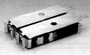
PART NUMBER: FTI-12x2A-1A (for one module):
Specifications:
Dimension of each module:
Length: 5.4 cm (2.12").
Height: 1.17 cm (0.46")
Width: 1.5 cm (0.63")
Power: 150 watts (5 volts DC @ 30 Amps per module)
Operation Frequency: 250 KHz - 500 KHz
Suitable for the following topologies:
Half-Bridge, Full-Bridge, Push-Pull
Output Voltage: 0 to 15 Volts DC
Input Voltage: up to 500 VAC depending on the number of modules and the number of turns
Schematic diagram of a flat transformer-inductor module:
 The secondary is configured
as a push-pull buck converter output, requiring only the
addition of a filter capacitor. The primary windings are
threaded through all the modules later. Terminals are
provided for direct connection to TO-247 dual rectifier
for minimum lead inductance. Top and bottom surfaces are
output conductors.
Applications:
DC to DC Converters.
Modules are optimized for 300 watts to 2000 watts
switching power supplies (600 watts requires 4 modules,
2000 watts requires 14 modules).

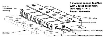
Turn Ratios: N x P : 1
N = Number of modules placed side by side
with holes aligned.
P = Number of primary windings through ALL the modules.
Example, for a turn ratio of 8:1, 600 watts:
Use N = 4 modules and P = 2 turns primary through all
modules.
Transformer Section:
Inductance (min.) of each
module, lm = 10 µ